
|
|
|
|
|
|
Home Site Search Contact Us Subscribe
|
|
|
|
INSIGHT: Creating an Arbor for Art in Fort Worth
Just how was Tadao Ando's design for Modern Art Museum of Ft. Worth translated into a concrete reality? The engineers explain the solutions that range from the exotic to the purely functional. by David B. Spires, P.E., Leo J. Galletta, P.E., and Leonard M. Joseph, P.E., S.E. December 3, 2002 More than five years ago, the directors and benefactors of the Modern Art Museum of Fort Worth, Texas, embarked on a journey from their cramped, leased location to a spacious facility designed by one of the world’s most celebrated architects. Six highly regarded architects were invited to submit designs for a new building, to be sited across the street from the renowned Kimbell Art Museum designed in the late 1960s by Louis Kahn. The submittals tried both to honor the Kimbell and to build on its most successful features. The entry by Tadao Ando, a self-taught practitioner based in Osaka, Japan, best addressed the museum’s aesthetic, functional, and contextual needs. In his vision, titled “An Arbor for Art,” a series of gallery modules echoing those at the Kimbell appear to rise from the wooded site like a grove of trees. For the modules, Ando proposed a building within a building: an outer, three-story glass curtainwall, shaded from the Texas sun by sweeping roof overhangs, surrounding massive inner gallery walls of architectural concrete. Using architectural concrete for structural systems normally covered with finishes demanded completely new approaches to design and construction. It required a team that worked together much more closely than usual to integrate the detailing and systems. To bring the concept to reality, the museum selected a design and construction team that included Kendall/Heaton Associates (KHA) of Houston, as the architect of record; Thornton-Tomasetti Engineers (TTE) of Dallas, for the structural design; CHPA Consulting Engineers (CHPA) of Houston, for the mechanical, electrical, and plumbing (MEP) systems design; and Linbeck Construction Company of Fort Worth, for pre-construction consulting and the construction contract. As the director of design and construction representing the owner’s interests, Peter Edward Arendt kept the team moving forward together. Construction began in August 1999 and was completed in September 2002. The new museum will be dedicated with an official ribbon cutting on December 14. By early accounts, it is already recognized as a work of art in its own right. The $65-million, 153,000-square-foot building includes 53,000 square feet of gallery and exhibit space, providing the museum with more than five times its former gallery space and more lighting and positioning options throughout. It also contains 5,600 square feet of classrooms, an inviting indoor/outdoor café, expanded parking, a larger bookstore, and a 250-seat auditorium. Within the main lobby, a sculpted post-tensioned architectural concrete bridge, detailed with Ando’s signature quarter-round cove soffits, links the gallery and the administrative areas at the second floor. Lanterns and Treetops The museum consists of five modules, adjacent to a 1.5-acre pond on its eastern end that will lend the galleries the appearance of “floating Japanese lanterns” after dark. Forty-foot-tall Y-shaped columns that express the “treetops” of the museum support the large roof overhangs at the pond end of the galleries. The roof system consists of long parallel strips, each a complex torsionally rigid “folded plate” of architectural concrete, from which lower roof strips are suspended. Sunlight passes through gaps in the high roofs, bounces off the low roofs, and enters the larger galleries through clerestory windows. Three of the five modules house only galleries, while the other two contain both exhibit space and other functions. The design team provided for a sixth gallery module just north of the current building limit in case additional gallery space was ever needed. In translating Ando’s concept into a functional structure, one of the first steps was to define the extent of architectural concrete walls within the galleries. The client felt that the continuous walls proposed would not allow enough flexibility for displaying the museum’s collection. The team worked to reduce the expanse of the walls while preserving Ando’s concept of a buffer system. In the final design, the walls remain at the ends of each gallery module, along prominent circulation areas, and wherever they were believed to be architecturally or structurally essential. The structural engineers next developed a range of workable and cost-effective approaches for the elaborate roof system. The initial design concept indicated a roof that floated above the gallery spaces using exposed steel beams supporting corrugated decking. Soon after his selection, Ando investigated other roof concepts, including various architectural concrete systems. All the schemes included a mirrored pair of folded plate elements over each 24-foot-wide gallery, forming a three-dimensional roof soffit. This approach was clearly Ando’s nod to the earlier Kimbell structure, where repeating architectural concrete barrel vaults successfully produced aesthetically appealing, diffuse lighting. In devising ways to support the high roof in the most straightforward manner possible, TTE developed nearly 20 different structural schemes, including various combinations of cast-in-place concrete, precast concrete, and steel framing. The schemes reflected that the folded plates would be exposed only in certain areas, so there were no constraints as to materials or techniques, provided that architectural concrete was used for the exposed surfaces. Up on the roof: valleys, wells, folded plates, and flat slabs The roof schemes that evolved could be divided into two conceptual categories. Some were single-layer systems with roof valleys open to the sky and crossed by “flying” beams transverse to the gallery runs. Cantilevered flat slab systems formed the large overhangs. Folded plates formed both open roof wells and gallery ceilings. In the second category, a generally flat roof deck over the galleries projected in the same plane to form the needed cantilevered overhangs, and folded plates below the flat deck formed the gallery ceilings. Because the rooftop would be out of view, and flat roofs would be easier to build and maintain than the rooftop wells, the flat-roof schemes were developed further. TTE and Linbeck worked together to explore construction options including steel framing clad with precast concrete, cast-in-place concrete, and even plaster finishes. Differences of opinion surfaced. Some argued for separate structural and cladding systems, questioning the value of placing carefully crafted architectural concrete where ultimately the surfaces would not be exposed. The team eventually deferred to Ando’s concept that the concrete elements be both beautiful and integral to the support of the structure. An all-concrete approach was selected. Once this direction was set, TTE investigated taking maximum advantage of the monolithic nature of concrete, including structural simplification. Earlier roof designs included regularly spaced beams across the long row of skylights centered over each 24-foot-wide gallery. The beams were needed to resist the tendency of the folded plates to rotate along their axes. But with a flat upper roof and an all-concrete structure, the roof above and folded plate below formed a closed hollow shape capable of resisting the torsion created by the weight of the large overhangs without the crossbeams. Torsional reactions are resisted at the gallery end walls. This inherent torsional strength proved to be even more valuable when supporting the low roof sections over the wider galleries. Hangers from the edges of the high roof created torsion there, but minimized the low roof spans. This allowed for a very shallow low roof structure – a 6.5-inch-thick post-tensioned slab – and high gallery ceilings. Cantilevers and columns At the pond end of the galleries, Ando envisioned the folded plate roof systems tapering upward, leaving only a flat, floating plane of overhanging architectural concrete that appeared to cantilever past the Y-shaped columns by the glass wall. Because of the sheer size of these cantilevers (24 feet long and 56 feet wide), the conceptual layouts had provided for upturned stiffening beams in two directions. Later, when it was decided to eliminate the beams, TTE proposed post-tensioning the existing flat slab in the transverse direction to provide stress and deflection control without upturned crossbeams. Linbeck implemented this revision with minimal impact, resulting in a much cleaner roofline. Many hours of team meetings were devoted to studying the Y columns and how they might best be built. These needed to appear cast-in-place and not compromised in appearance in any way, as might have occurred using typical precasting techniques. Due to the great size of these columns – 39 feet tall and 24 feet wide – TTE proposed that they be site-cast in pieces and attached using concealed connections, but Linbeck suggested a fully cast-in-place design. As Linbeck’s construction planning progressed, it became clear that the sloping forks could not be cast in place because the vibrators would damage the forms during concrete placement. Linbeck was convinced the forks must be cast in a vertical position to achieve the high-quality finish Ando required, and asked TTE to take another look at the early proposal to cast the components as pieces. TTE studied how best to accomplish this, and one critical feature made the entire concept work. As in the remainder of the building, at 18 feet above the first floor a small reveal for all vertical concrete surfaces had been detailed. This joint also appeared at the base of the crotch in the Y columns, and became the key to assembling the pieces in a concealed fashion. Casting trunks and forks First, the vertical portion (or “trunk”) of the assembly was cast up to the reveal joint, with protruding post-tensioning bars and an alignment and erection safety stub. Then the forks were cast vertically elsewhere on the site, with embedded steel welding plates and female reinforcement bar couplers placed in their lower ends. The forks were placed in a steel cradle at grade that Linbeck devised to secure them and to allow for fine adjustments of position. With the forks secure and aligned, the connecting plates and reinforcement bars were coupled together in the crotch, and then the crotch concrete was placed, casting in sleeves for the post-tensioning bars coming up from the trunk and a receiver for the safety stub. Next, Linbeck attached a lifting device to the upper end of the forks, which maintained the correct slope and relative position, and used cranes to lift the completed upper assembly into place on top of the waiting trunk. All that remained was to carefully lower the assembly into place, check the alignment, and tighten the nuts on the protruding post-tensioning bars. The reveal joint allowed for adjustment shims and provided a natural place to grout the two pieces together in a concealed manner. The sleeves for the post-tensioning bars were then pressure-grouted, and a mortar cap was hand-placed. Directly behind the Y columns stand three-story-high glass and aluminum curtainwalls that form the outer skin of most of the building. Conventional wide-flange steel shapes were architecturally acceptable in typical cases. The corner column proved much more difficult – Ando wanted the corner column to disappear in profile, while the project curtainwall consultant had given TTE stringent deflection limitations in the plane of the glass. A wind tunnel test, performed for the benefit of both the primary structure and the building cladding, showed that the corner column could be reduced to a simple square tube. As a result of simplifying the corner column and slimming the typical backup columns, the aesthetic was achieved – and saved the client more than $150,000. A favorite destination in the new building will likely be the café where the seating area resides under a huge ellipse of post-tensioned architectural concrete – 75 feet long, 50 feet wide, and 6 to 24 inches thick – projecting out over the adjacent pond. Two massive 36-inch-diameter concrete columns, laterally braced by a quarter-circle architectural concrete wall and the main building itself, support the ellipse for gravity loads. The giant roof appears to knife into the main structure while providing support for the curtainwall above it. As the new concrete, glass, and metal “arbor for art” took shape, the reward for the team’s effort became visible to the public, to the staff, and to all those involved in the planning and execution. David
B. Spires, P.E., is an associate and Leo J. Galletta, Ph.D., P.E., is a senior
vice president for Thornton-Tomasetti
Engineers, in Dallas. Leonard M. Joseph, P.E., S.E., is a senior vice
president in the firm’s New York City office. Project
Credits Owner:
MPA Foundation, Fort Worth, Texas Design
Architect: Tadao Ando Architect & Associates, Osaka, Japan Architect
of Record: Kendall/Heaton Associates, Inc., Houston Consulting
Architect: Richard Fitzgerald & Associates, Houston Structural
Design: Thornton-Tomasetti Engineers, Dallas Civil
Engineer: Huitt-Zollars, Inc., Fort Worth, Texas Landscape
Architect: SWA Group, Houston Water
Feature Consultant: Waterscape Consultants, Inc., Houston Lighting
Consultant: George Sexton Associates, Washington, DC Curtainwall
Consultant: Peter M. Muller, Inc., Houston Acoustical
Consultant: Cerami & Associates, Inc., New York City MEP
Systems Design: CHPA Consulting Engineers, Houston Contractor: Linbeck Construction Company, Fort Worth, Texas |
(click on pictures to enlarge) 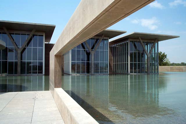 (David B. Spires/Thornton-Tomasetti Engineers) Architectural concrete beams and columns frame the view toward the galleries and reflecting pond, as seen from the café terrace.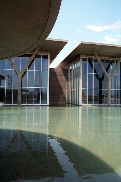 (David B. Spires/Thornton-Tomasetti Engineers) Gallery roof cantilevers, supported by architectural concrete Y-columns, hover over the reflecting pond (the giant elliptical café roof left foreground).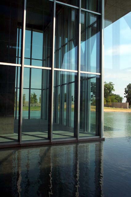 (David B. Spires/Thornton-Tomasetti Engineers) Floors float just inches above the reflecting pond, with architectural concrete site walls beyond.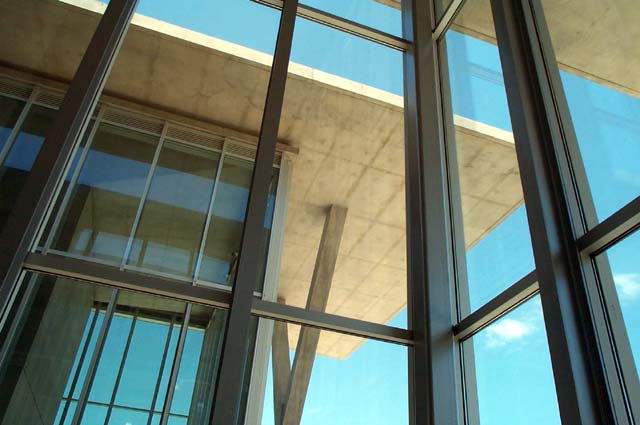 (David B. Spires/Thornton-Tomasetti Engineers) Outsize architectural concrete roof cantilevers shade the east ends of the galleries.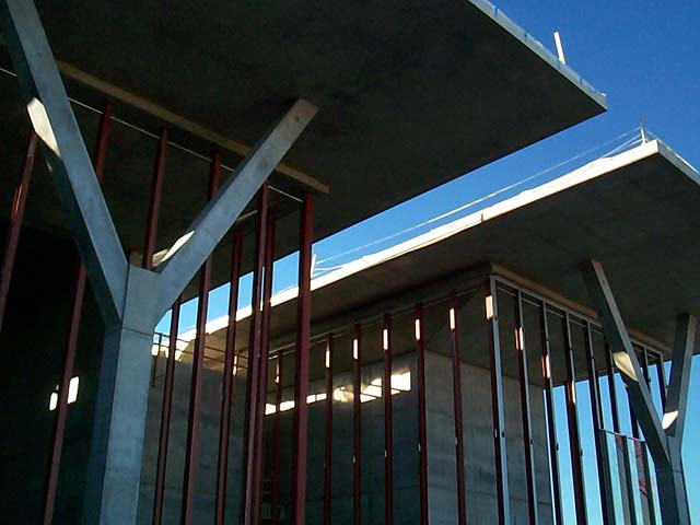 (David B. Spires/Thornton-Tomasetti Engineers) The east end of the galleries under construction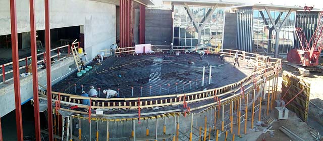 (David B. Spires/Thornton-Tomasetti Engineers) Cafe Terrace roof under construction, just before installation of the post-tensioning tendons.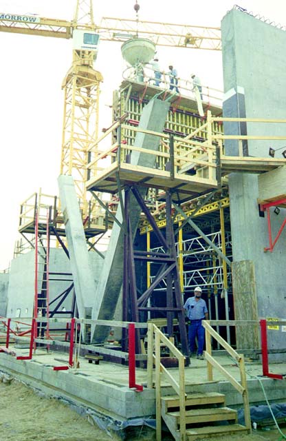 (David B. Spires/Thornton-Tomasetti Engineers) The cradle built to hold the Y-column forks in position (stage 2 of Y-column assembly method pictured below).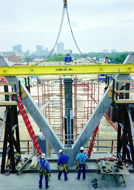 (David B. Spires/Thornton-Tomasetti Engineers) The Y-column assemblies ready for lifting onto the stem (stage 5 of Y-column assembly method pictured below).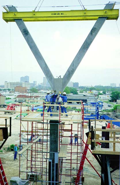 (David B. Spires/Thornton-Tomasetti Engineers) The Y-column assemblies being set in place atop the stem (stage 6 of Y-column assembly method pictured below)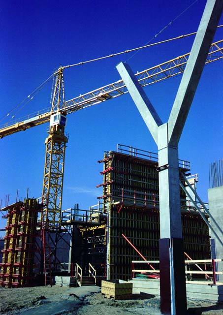 (David B. Spires/Thornton-Tomasetti Engineers) The first Y-column completed, with the cradle used to cast the forks (stage 2 of Y-column assembly method pictured below) in the background.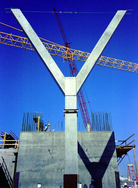 (David B. Spires/Thornton-Tomasetti Engineers) The first completed Y-column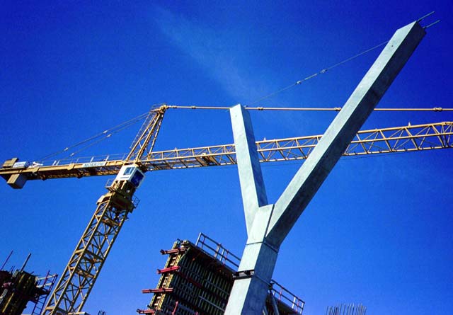 (David B. Spires/Thornton-Tomasetti Engineers) The first completed Y-column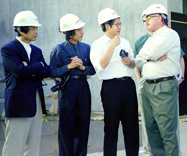 (David B. Spires/Thornton-Tomasetti Engineers) Tadao Ando and his team (l-r): Ando, Masataka Yano, Kulapat Yantrasast, Paul Sipes/Linbeck Construction (that's Rollie Childers of KHA hidden behind Paul).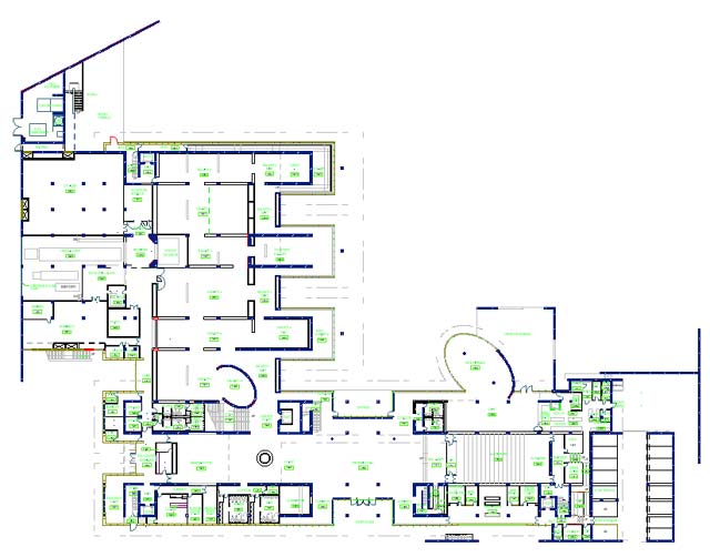 (Thornton-Tomasetti Engineers) Plan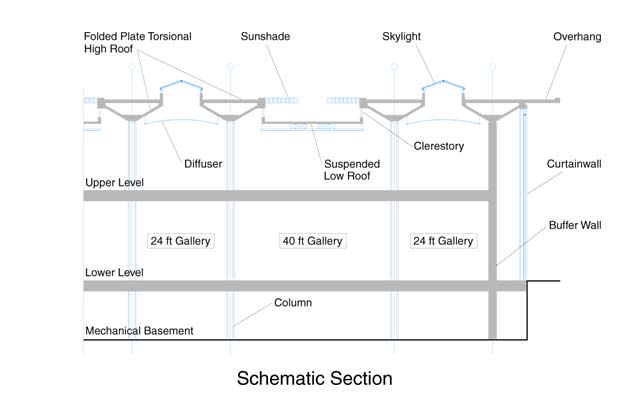 (Thornton-Tomasetti Engineers) Section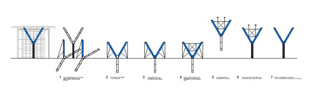 (Thornton-Tomasetti Engineers) Y-column assembly method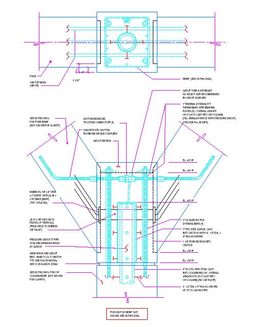 (Thornton-Tomasetti Engineers) Assembly detail at Y-column crotch |
© 2002 ArchNewsNow.com